Views: 0 Author: Site Editor Publish Time: 2026-08-05 Origin: Site
Modern high-voltage applications place escalating demands on power electronics. Systems like electric vehicle (EV) inverters, renewable energy grid ties, utility-scale energy storage, and industrial pulsed-power networks require components that handle extreme electrical stress. Engineers face a constant challenge when specifying dielectric materials. These materials must prevent catastrophic electrical breakdown, manage high ripple currents, and survive intense thermal cycles. They also need to maintain volumetric efficiency without degrading over decades of continuous operation.
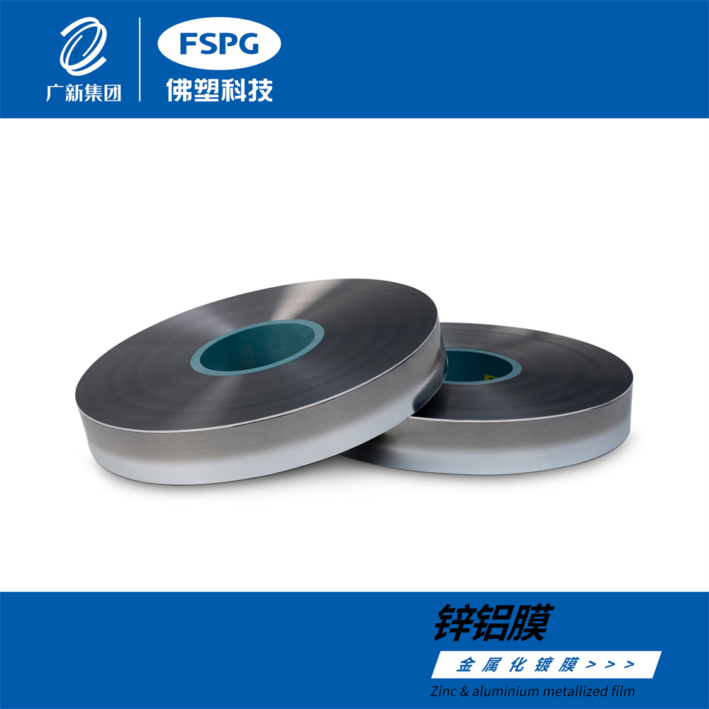
Biaxially oriented polypropylene has emerged as the dominant dielectric material for these demanding applications. The unique molecular alignment and electrical properties of BOPP Capacitor Film solve the high-voltage reliability equation. By offering exceptional dielectric strength and ultra-low losses, this material ensures stable performance in mission-critical environments. Understanding how this film performs under stress helps engineers optimize capacitor designs for next-generation power systems.
Superior Dielectric Strength: BOPP offers an exceptionally high breakdown voltage (typically >600 V/µm), allowing for thinner films and more compact high-voltage capacitor designs.
Ultra-Low Losses: A near-zero dissipation factor (Tan Delta) ensures minimal heat generation and prevents thermal runaway, even under severe high-frequency ripple currents.
Fail-Safe Reliability: Metallized BOPP architectures feature a self-healing mechanism that clears localized faults without causing catastrophic short circuits.
Application-Specific Trade-offs: While highly efficient electrically, engineers must account for BOPP’s thermal limitations (typically capping at 105°C) and design appropriate thermal management, voltage derating, or transition to emerging nanostructured alternatives where necessary.
High-voltage power film capacitors typically operate within thresholds ranging from 1kV to well over 100kV. At these levels, the electrical stress on the dielectric material is immense. Dielectric breakdown in mission-critical power systems leads to severe consequences. System failure, arc flash incidents, fire risks, and costly industrial downtime are common results of component failure. The baseline requirement for any dielectric is clear. It must provide maximum insulation resistance while maintaining the thinnest possible profile. This optimizes capacitance per unit volume, following the fundamental equation where capacitance equals permittivity times area divided by thickness.
To understand the scale of these requirements, we can look at typical operational voltages across different engineering sectors. Each sector demands specific dielectric performance to prevent breakdown.
Application Sector | Typical Voltage Range | Primary Dielectric Stress Factor |
|---|---|---|
EV Traction Inverters | 400V - 800V DC | High ripple current and rapid switching transients. |
Renewable Grid Ties (Solar/Wind) | 1kV - 3.3kV DC | Continuous high DC bias and thermal cycling. |
Utility Energy Storage | 1.5kV - 5kV DC | Long-term charge/discharge cycling and ESR heating. |
Pulsed Power Systems | 10kV - 100kV+ DC | Extreme dV/dt pulse discharge and corona risk. |
Energy storage systems subject capacitors to high ripple currents. These currents interact with the Equivalent Series Resistance (ESR) of the component, leading to internal heat generation through I²R losses. Effective thermal management is a strict success criterion. The dielectric material must resist thermal degradation over time. It must maintain stable capacitance values across its entire rated temperature range. Furthermore, it needs to sustain millions of charge-discharge cycles without failure. Materials that cannot dissipate heat efficiently will experience thermal runaway, leading to rapid component destruction.
When evaluating thermal stability, engineers look for specific failure modes that indicate a dielectric is not suited for the application. Recognizing these modes early prevents catastrophic system failures.
Capacitance drift exceeding 5% over the rated temperature range.
Accelerated increase in ESR due to localized heating.
Physical deformation or melting of the dielectric layers.
Dielectric absorption causing residual voltage buildup.
Complete thermal runaway leading to a dead short.
The manufacturing process of Capacitor Grade BOPP Film involves stretching the polypropylene resin in both machine and transverse directions. This biaxial orientation aligns the polymer chains and eliminates microscopic voids. The result is a significant enhancement in both mechanical tensile strength and dielectric integrity. Standard industry metrics show that oriented polypropylene achieves breakdown voltages exceeding 600 V/µm. This performance vastly outpaces non-oriented films and many alternative polymers, allowing engineers to design thinner, more efficient capacitor windings.
The orientation process directly dictates the final electrical properties. By controlling the stretch ratios and annealing temperatures, manufacturers tune the film for specific high-voltage applications.
Material Type | Typical Breakdown Voltage (V/µm) | Dielectric Constant (1kHz) |
|---|---|---|
Capacitor Grade BOPP | > 600 | 2.2 |
Standard Polyester (PET) | 400 - 500 | 3.3 |
Polyphenylene Sulfide (PPS) | 300 - 400 | 3.0 |
Non-Oriented Polypropylene | < 200 | 2.2 |
Polypropylene features a non-polar molecular structure. This characteristic results in extremely low dielectric absorption and dissipation factors, typically measuring less than 2 × 10⁻⁴ at 1 kHz. Low ESR and Equivalent Series Inductance (ESL) are critical for high-frequency switching environments. Systems utilizing Silicon Carbide (SiC) or Gallium Nitride (GaN) inverter topologies switch at very high speeds. The near-zero loss profile of BOPP ensures that the capacitor can handle these rapid switching cycles without generating excessive heat or risking thermal runaway.
Metallized film architectures provide a unique self-healing capability. When a localized dielectric puncture occurs due to a voltage transient, a microscopic short circuit forms. The intense heat generated at this fault instantly vaporizes the ultra-thin metal electrode surrounding the puncture. This vaporization isolates the fault from the rest of the circuit. The outcome is a microscopic loss of total capacitance, usually in the pico-farad range, rather than a catastrophic dead-short. This mechanism drastically extends the operational lifespan and reliability of the component.
The self-healing process happens in a fraction of a second. It follows a specific sequence of physical events that protect the overall capacitor structure.
A high-voltage transient exceeds the local dielectric strength of the film.
A microscopic puncture occurs, creating a conductive path between electrodes.
High fault current flows through the puncture, generating intense localized heat.
The ultra-thin metallization layer (zinc or aluminum) vaporizes around the fault.
The vaporized metal expands and blows outward, clearing the conductive path.
The fault is isolated, and normal capacitor operation resumes with negligible capacitance loss.
Polyester (PET) offers higher operating temperatures and better volumetric efficiency at lower voltages. However, BOPP vastly outperforms PET in high-voltage dielectric strength, insulation resistance, and high-frequency loss profiles. For applications exceeding 1kV, BOPP is the clear choice. Polyphenylene Sulfide (PPS) serves as a high-temperature alternative. While PPS can operate in hotter environments, BOPP maintains a superior cost-to-performance ratio. Its self-healing reliability in standard high-voltage ranges makes it the preferred option for most power electronics designs.
Film technology contrasts sharply with Class 1 and Class 2 ceramics. Ceramic capacitors often suffer from severe DC bias capacitance loss. They also present micro-cracking risks under mechanical stress and generate piezo-electric noise. Aluminum electrolytic capacitors have higher ESR and lower ripple current capacity. They face polar voltage limitations and suffer from shorter lifespans due to electrolyte dry-out. BOPP film eliminates these issues, providing stable, long-lasting performance in high-voltage AC and DC applications.
Engineers must weigh these differences carefully during the component selection phase. The right choice depends heavily on the specific demands of the circuit.
Dielectric Technology | Primary Advantage | Primary Limitation | Best Use Case |
|---|---|---|---|
BOPP Film | High voltage, low loss, self-healing. | Temperature limit (105°C). | High-voltage DC links, snubbers. |
Aluminum Electrolytic | High bulk capacitance per volume. | High ESR, limited lifespan. | Low-frequency bulk filtering. |
Class 2 Ceramic (X7R) | Compact size, surface mountable. | DC bias capacitance loss. | Low-voltage decoupling. |
PET Film | Good volumetric efficiency. | Higher high-frequency losses. | General purpose low-voltage AC. |
Emerging advancements are pushing the boundaries of dielectric technology. Multi-layer nanostructured co-extruded films, such as NanoPlex technology, layer BOPP with other high-temperature polymers. These next-generation films aim to surpass the traditional thermal limits of polypropylene. They seek to operate at higher ambient temperatures while preserving the excellent self-healing and dielectric properties that make standard BOPP so effective. Engineers monitor these developments for future high-density power applications.
Engineers must analyze mechanical and volumetric trade-offs when selecting construction types. Wire-wound metallized film designs are best for space-saving. They take up two to three times less space than foil armature constructions. They also enable robust self-healing capabilities in high-voltage DC-link applications. Conversely, film/foil constructions are necessary for extreme high-current pulse applications, such as snubbers. In these environments, the ultra-thin metallization layer of standard films would melt under peak dV/dt stresses.
Series-wound internal configurations within a single capacitor casing offer specific design advantages. These designs divide the total applied voltage across multiple internal capacitive sections connected in series. This division significantly reduces the voltage stress on individual layers of the film. Key applications for this configuration include low-value, high-voltage AC/DC filtering, snubber networks, and voltage dividers. In these circuits, safety and high partial discharge inception voltages are critical for long-term stability.
Environmental protection requirements dictate the choice of packaging. Boxed types, which feature an epoxy-filled plastic case, provide superior protection against humidity, mechanical shock, and flame retardancy. This protection comes at the expense of compactness. Unboxed or wrap-and-fill types are better suited for strictly controlled, space-constrained environments. When weight and volume are premium constraints, unboxed configurations offer the necessary performance without the added bulk of a plastic casing.
The primary limitation of polypropylene is its melting point and structural degradation at high temperatures. Capacitors typically require voltage derating above 85°C, with hard operational limits around 105°C. Engineers must implement strict mitigation strategies. Active cooling systems help maintain safe operating temperatures. Applying strict voltage derating curves ensures the dielectric is not overstressed. Specifying thicker, high-purity films provides an additional safety margin for components operating in high-ambient environments.
Implementing effective thermal management requires a multi-faceted approach. Design teams usually deploy several strategies simultaneously.
Integrate forced air or liquid cooling plates near the capacitor banks.
Apply strict voltage derating curves based on manufacturer specifications.
Increase the physical spacing between capacitors to improve natural convection.
Specify thicker dielectric films to reduce electrical stress at higher temperatures.
Partial discharge, or corona, poses a significant risk in high-voltage AC applications. These micro-discharges can erode the film over time and cause premature dielectric breakdown. Manufacturing and design-level mitigations are essential. Utilizing series-wound internal structures helps manage electric fields. Oil-impregnation or vacuum-potted epoxy sealing completely eliminates air pockets and voids where corona discharges initiate. Eliminating these voids is critical for extending the lifespan of high-voltage AC capacitors.
Specifying ultra-high-purity, capacitor-grade resins is critically important. Impurities act as localized electric field concentrators, leading to early failure. Film thickness consistency, often down to sub-2-micron levels, directly impacts the final component's failure rate. Strict quality control ensures batch-to-batch reliability in mass production. Engineers must verify that suppliers maintain rigorous standards to guarantee the long-term performance of the finished capacitors.
To move forward with your design:
Review specific manufacturer datasheets to verify breakdown voltage and ESR specifications.
Request dielectric loss curves tailored to your specific operating frequencies and temperatures.
Consult with field application engineers to determine the optimal film thickness and metallization profile.
Evaluate packaging options based on your environmental and spatial constraints.
A: BOPP film capacitors handle extremely high voltages, ranging from 1kV to over 100kV. The specific rating depends on film thickness, series-wound internal sections, and overall construction. Proper design ensures dielectric stress remains safely below the breakdown threshold.
A: When a voltage transient punctures the dielectric, it creates a microscopic short. The intense heat instantly vaporizes the ultra-thin metal layer surrounding the puncture. This clears the short circuit and isolates the fault, resulting in a tiny loss of capacitance rather than component failure.
A: BOPP has a non-polar molecular structure, resulting in a much lower dissipation factor than PET. It generates significantly less internal heat under high-frequency ripple currents. In fast-switching applications like SiC or GaN inverters, BOPP prevents thermal runaway.
A: BOPP film softens and loses mechanical and dielectric integrity at high temperatures. Standard operational limits are around 105°C, with voltage derating required above 85°C. Exceeding these limits leads to structural degradation, increased leakage current, and catastrophic breakdown.
A: Yes, but construction type matters. For extreme high-current pulse applications with high dV/dt stresses, a film/foil construction is required. The ultra-thin metallization in standard films melts under peak current stresses, so solid metal foils handle the surge.
A: Capacitor grade film uses ultra-high-purity resins to eliminate microscopic impurities that concentrate electric fields. It is manufactured with extreme precision to ensure uniform thickness down to sub-2-micron levels. Standard commercial BOPP lacks this purity and consistency.